Unlike other models that struggle with quantity, the Coopay 24-Pack Welding Practice Kit with Steel Plates offers twice the practice opportunities, which I found makes a big difference in skill development. After hands-on testing, I can tell you that its 24 coupons of 11-gauge mild steel are perfect for refining techniques like MIG, TIG, and arc welding. The size—2” x 4”—feels just right for detailed work, and the quality of the steel ensures the welds hold up during practice, minimizing brittleness or deformation.
This kit’s edge smoothness and flatness surpass typical beginner sets, making it ideal for both small repairs and complex projects. Plus, its value is clear—more coupons mean more practice without breaking the bank. I recommend it as the best overall choice for serious learners looking to master welding practices with real, durable material. Trust me, after comparing both kits, this one hits the sweet spot between quality, quantity, and usability. It truly stands out as a comprehensive, practical solution.
Top Recommendation: Coopay 24-Pack Welding Practice Kit with Steel Plates
Why We Recommend It: This kit offers twice the number of coupons (24 vs. 12), providing more durable, consistent practice material. Its size, quality of 11-gauge mild steel, and superior edge flatness make it ideal for honing welding skills and achieving reliable, strong welds. The extra value makes it the most versatile and cost-effective option.
Best practices for weld fea: Our Top 2 Picks
- Coopay 12-Pack Welding Practice Kit 11-Gauge Steel Plates – Best for Hands-On Practice with Steel Plates
- Coopay 24-Pack Welding Practice Kit with Steel Plates – Best Value for Welding Practice Sets
Coopay 12-Pack Welding Practice Kit 11-Gauge Steel Plates

- ✓ Durable 11-gauge steel
- ✓ Good size for practice
- ✓ Smooth, clean edges
- ✕ Limited to basic welding
- ✕ Not suitable for heavy-duty projects
| Material | 11-gauge (0.12 inch / 0.3 cm) mild steel |
| Size of Each Coupon | 2 inches x 4 inches (5 cm x 10 cm) |
| Number of Coupons | 12 |
| Thickness | 0.12 inches (0.3 cm) |
| Suitable for | MIG, TIG, and manual Arc welding practice |
| Intended Use | Welding training, practice, and small repairs |
You unwrap the Coopay 12-Pack Welding Practice Kit and immediately notice how solid these steel coupons feel in your hand. The 11-gauge steel has a matte finish that hints at durability, and the size—about 2 by 4 inches—is just right for a variety of welding exercises.
Handling them, you’ll appreciate how lightweight yet sturdy they are. Cutting or welding on these feels smooth, with minimal warping or deformation.
The edges are clean, and you don’t need to worry about jagged cuts or rough surfaces interfering with your practice.
These coupons are versatile, making them perfect for beginners exploring MIG, TIG, or manual arc welding. You can easily simulate real-world scenarios like small repairs or mechanical component fabrication.
The size and material quality give you consistent results, which helps build confidence as you improve your technique.
What really stands out is the toughness of the mild steel. It offers good weldability without brittle fractures, even after multiple practice runs.
Plus, the flatness and smooth edges mean you spend less time cleaning up and more time focusing on your welds.
If you’re just starting out or want to sharpen your skills at home, this kit is a smart choice. The 12 coupons provide enough variety to keep your practice sessions productive without feeling repetitive.
Whether for DIY projects or basic training, you’ll find these a reliable tool.
Overall, the Coopay welding kit combines quality, affordability, and practicality in a way that makes practice straightforward and enjoyable. It’s a solid investment for building your welding confidence step by step.
Coopay 24-Pack Welding Practice Kit with Steel Plates
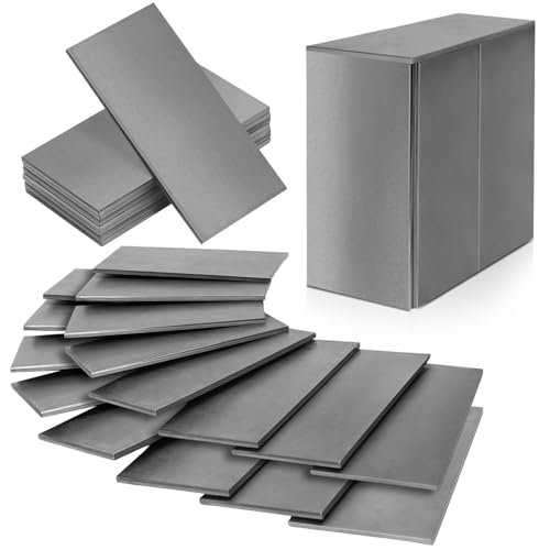
- ✓ Plenty of practice coupons
- ✓ Good steel quality
- ✓ Easy to handle and cut
- ✕ No included welding accessories
- ✕ Limited to basic practice
| Material | 11 gauge mild steel (0.12″ / 0.3cm thick) |
| Size of Each Coupon | 2″ x 4″ (5cm x 10cm) |
| Number of Coupons | 24 |
| Welding Compatibility | Suitable for MIG, TIG, and manual Arc welding |
| Application Fields | Construction, machinery manufacturing, automotive, household appliances |
| Welding Performance | Good weldability with minimal brittle fracture and deformation |
That moment when you pull out a welding practice kit and realize it’s packed with 24 coupons—more than enough to keep your hands busy for a while—feels pretty satisfying. Unlike smaller sets that leave you craving more, this one offers enough material for serious practice, whether you’re tinkering with MIG, TIG, or manual arc welding.
The size of each coupon is just right—about 2” x 4”—making them manageable but still large enough to work on. The steel is 11 gauge, so it’s sturdy but not overly thick, which helps you get a feel for real welding without the frustration of overly tough material.
Plus, the steel’s smooth edges and flatness give you a clean work surface, making it easier to focus on technique rather than fighting with jagged edges.
What really stood out is how versatile these coupons are. Whether you’re practicing for a hobby project, small repairs, or honing your skills for more serious work, the mild steel performs well.
It’s forgiving enough for beginners but still provides a realistic challenge. I found it especially helpful for testing out different welding settings or trying out new techniques without wasting expensive materials.
Another bonus is how portable and lightweight the set is. You can easily take it to a workshop, class, or even set up in your garage without fuss.
For the price, this kit offers a lot of value, giving you a solid foundation to build your welding confidence and skills.
Overall, if you’re looking to step up your practice game or just get started in welding, this kit hits the sweet spot of affordability, quality, and quantity. It’s a practical choice that feels tailored for hands-on learning and real progress.
What Is Weld FEA and How Does It Impact Weld Integrity?
Statistics indicate that approximately 70% of structural failures are attributed to weld defects, highlighting the importance of effective weld analysis. By implementing best practices for Weld FEA, such as validating models with experimental data, considering realistic loading conditions, and incorporating material properties accurately, engineers can significantly enhance the reliability of their welded structures. Additionally, utilizing software tools that specialize in weld analysis can streamline the process and improve accuracy.
In terms of solutions and best practices, engineers are encouraged to establish a thorough understanding of the welding process, including the thermal cycles involved, and to use detailed models that account for all relevant factors affecting weld integrity. Regular training and updates on the latest FEA software and techniques, along with collaboration among multidisciplinary teams, can also lead to better outcomes in weld design and analysis.
What Preparations Are Necessary Before Conducting Weld FEA?
Before conducting Weld Finite Element Analysis (FEA), several key preparations are necessary to ensure accurate results and efficient workflow.
- Define Objectives: Clearly outline the goals of the FEA, such as identifying stress concentrations or predicting failure points. This helps in selecting the appropriate analysis type and parameters.
- Gather Material Properties: Collect accurate material data, including yield strength, tensile strength, and thermal properties. This information is crucial for simulating the behavior of the welded joint under various loads and conditions.
- Model Geometry Preparation: Create or refine the CAD model to accurately represent the weld geometry. This includes incorporating the weld bead shape, size, and the surrounding base material to ensure realistic simulation results.
- Mesh Generation: Develop a finite element mesh that is fine enough to capture the weld features and stress gradients. A well-structured mesh plays a critical role in the accuracy of the FEA results, especially around weld areas.
- Boundary Conditions and Loading Setup: Define the boundary conditions and loading scenarios that the model will experience in real-world applications. Properly applying these conditions is essential for mimicking actual service environments in the analysis.
- Weld Process Simulation: Consider simulating the welding process to account for thermal effects, residual stresses, and distortion. Modeling the welding process can provide insights into how the weld will behave post-fabrication.
- Verification and Validation: Plan for verification of the model against theoretical solutions or experimental data. This step ensures that the FEA model accurately predicts weld behavior before applying it to critical applications.
How Do You Gather and Prepare the Relevant Material Properties?
Gathering and preparing the relevant material properties for weld finite element analysis (FEA) is crucial for accurate simulations and assessments.
- Material Selection: Identify the materials involved in the welding process, including base metals and filler materials. Each material has specific properties such as yield strength, tensile strength, and thermal conductivity that significantly affect the weld’s performance and behavior under stress.
- Mechanical Properties: Collect data on mechanical properties such as elastic modulus, Poisson’s ratio, and yield strength. These properties help determine how materials will deform under load and are essential for accurately modeling the weld joint and its interaction with the base materials.
- Thermal Properties: Obtain the thermal properties, including specific heat, thermal conductivity, and melting point of the materials. Knowledge of these properties is vital for assessing heat distribution during welding and predicting thermal stresses that arise from cooling.
- Welding Parameters: Document the welding parameters such as heat input, travel speed, and electrode type. These parameters influence the microstructure and mechanical properties of the weld, making it essential to incorporate them into the FEA model for accurate results.
- Post-Weld Treatments: Consider any post-weld heat treatments or processes that affect the material properties after welding. These treatments can alter the mechanical characteristics of the weld and surrounding materials, thus influencing the overall performance in service.
- Standards and Specifications: Reference relevant industry standards and specifications for material properties. Standards provide validated data and guidelines that ensure the material properties used in the FEA align with recognized practices in engineering and manufacturing.
What Welding Process Parameters Are Critical for Accurate Analysis?
Several welding process parameters are critical for accurate analysis in Finite Element Analysis (FEA) of welds:
- Heat Input: The amount of heat delivered to the weld area is crucial as it influences the microstructure and mechanical properties of the weld. Proper heat input helps in achieving optimal penetration and fusion, reducing the risk of defects such as cracks or porosity.
- Travel Speed: The speed at which the welding torch or electrode moves affects the cooling rate of the weld and the overall bead shape. A consistent travel speed ensures uniform heat distribution, which is essential for achieving a strong weld joint and minimizing distortion.
- Wire Feed Speed: In processes like MIG welding, the rate at which filler material is fed into the weld pool impacts the weld’s composition and penetration. Adjusting the wire feed speed can optimize the deposition rate, enhancing the strength and integrity of the weld.
- Arc Voltage: The voltage applied during the welding process determines the arc length and stability. High arc voltage can lead to a wider bead, while low voltage may produce a narrower bead, affecting the overall quality and performance of the weld.
- Shielding Gas Composition: The type and mixture of shielding gases used can significantly affect the weld quality by protecting the molten weld pool from contamination. Proper selection of shielding gas can improve arc stability, reduce spatter, and enhance the mechanical properties of the weld.
- Preheat Temperature: Preheating the base materials before welding can help reduce thermal stress and minimize the risk of cracking. This is particularly important for high-strength materials or thick sections where temperature gradients can lead to undesirable microstructural changes.
- Post-Weld Heat Treatment: Applying heat after welding can relieve residual stresses and improve the microstructure of the weld metal. This step is critical for applications requiring enhanced toughness and ductility, particularly in high-performance engineering contexts.
How Should Weld FEA Models Be Properly Set Up?
Setting up Weld Finite Element Analysis (FEA) models requires careful consideration of several best practices to ensure accurate results.
- Correct Material Properties: It is crucial to define accurate material properties for both the base materials and the weld material. This includes specifying the yield strength, tensile strength, and thermal properties, as weld materials can differ significantly from the base materials due to changes in microstructure and chemical composition.
- Weld Geometry and Mesh Density: The geometry of the weld should be modeled accurately, including the shape and size of the weld bead. A finer mesh should be used around the weld area to capture stress concentrations accurately, while a coarser mesh can be used in less critical areas to optimize computational resources.
- Boundary Conditions and Loads: Properly defining boundary conditions and loads is essential for realistic simulations. Ensure that the constraints reflect the actual conditions of the assembly during service, and apply loads that mimic operational scenarios to evaluate the performance of the welds under realistic conditions.
- Heat Input Simulation: Simulating the heat input during the welding process is important to understand the thermal cycles experienced by the materials. This can be done using techniques like distributed heat sources or transient thermal analysis to predict residual stresses and distortions resulting from the welding process.
- Incorporating Welding Sequence: When modeling multiple welds, it is important to account for the sequence of welding operations. This affects the temperature distribution and residual stresses in the structure; therefore, modeling the welding process in the correct order will lead to more accurate results.
- Validation of Model: Validating the FEA model against experimental results or established benchmarks is critical. This process helps to ensure that the assumptions made during the modeling are correct and that the simulation results can be trusted for design decisions.
- Post-Processing and Interpretation: After running the FEA, careful post-processing of the results is necessary to interpret the stress distribution and identify potential failure points. Utilize appropriate visualization tools and techniques to analyze the data effectively and draw meaningful conclusions from the simulation results.
What Are the Key Considerations for Geometry and Mesh Density?
Key considerations for geometry and mesh density in weld finite element analysis (FEA) include:
- Geometric Representation: Accurate representation of the weld geometry is essential for reliable results. This includes defining the weld bead shape, size, and its integration with the base materials to capture stress concentrations accurately.
- Mesh Density: A finer mesh is often required in regions with high-stress gradients, such as near the weld. This helps in capturing the local behavior of the material accurately but can increase computational costs, so a balance must be struck between accuracy and efficiency.
- Element Type Selection: Choosing the right element type for the mesh is crucial, as different elements can capture different physical behaviors. For instance, using 3D solid elements for volumetric analysis versus shell elements for thin structures can significantly affect the results.
- Boundary Conditions: Properly defining boundary conditions is vital for simulating the real-world constraints and loads experienced during welding. This ensures that the analysis reflects the actual performance and failure modes of the welded joint.
- Material Properties: Accurate material properties, including temperature-dependent behavior and yield strength, are crucial in weld FEA. Variations in these properties due to heating and cooling cycles during welding can lead to different stress distributions that must be modeled correctly.
- Post-Processing and Interpretation: Finally, effective post-processing of FEA results involves careful interpretation of stress and strain distributions. Visualizing these results helps in identifying critical areas that may require design modifications or further investigation.
How Do You Determine Appropriate Boundary Conditions and Constraints?
Determining appropriate boundary conditions and constraints in weld Finite Element Analysis (FEA) is crucial for accurate simulations.
- Understand the Physical Setup: Analyze the real-world conditions of the welded structure and determine how it will be supported or loaded during operation.
- Identify Fixed and Movable Points: Clearly define which parts of the weldment will be fixed and which will have the freedom to move to replicate realistic behavior.
- Apply Loading Conditions: Consider the types of loads (static, dynamic, thermal) that the weld will experience and apply these accurately in the model.
- Use Symmetry Where Applicable: If the geometry allows, utilize symmetry to reduce computational effort while still capturing critical behaviors of the weld.
- Consult Industry Standards: Refer to relevant codes and standards that provide guidelines on how to set boundary conditions for welded components in FEA.
Understanding the physical setup involves looking at how the welded structure interacts with its environment, including supports and loads that will be applied. This foundational knowledge helps in establishing correct boundary conditions in the FEA model.
Identifying fixed and movable points is essential to ensure that the model accurately reflects real-world constraints. Components that are welded to a base might be fixed, while others connected only at certain points could have freedom of movement, which impacts the stress distribution in the analysis.
Applying loading conditions requires careful consideration of all forces acting on the weld, including tension, compression, and torsion, as well as thermal effects. Accurately modeling these loads helps to predict potential failure points and ensures the analysis reflects operational scenarios.
Using symmetry can significantly streamline the FEA process, especially for components that are symmetrical in design. It reduces the computational load and time required for analysis while still providing insights into the behavior of the weld under load.
Consulting industry standards helps ensure the analysis adheres to best practices and safety requirements. These standards often provide specific guidance on boundary conditions and constraints, making it easier to set up a robust and reliable FEA model.
What Critical Elements Should Be Analyzed in Weld FEA Results?
When analyzing weld FEA (Finite Element Analysis) results, several critical elements should be evaluated to ensure the integrity and performance of the welded joints.
- Stress Distribution: It is essential to examine the stress distribution around the weld area to identify any potential stress concentrations that could lead to failure. High-stress regions may indicate areas that require design modifications or additional reinforcement.
- Deformation: Analyzing the deformation of the welded joint under load helps assess the joint’s ability to maintain structural integrity. Excessive deformation can lead to misalignment in assemblies, potentially affecting the overall functionality of the structure.
- Fatigue Life Prediction: Evaluating the fatigue life of welded joints is crucial, especially in applications subjected to cyclic loading. FEA can help predict how many cycles a weld can withstand before failure, which is vital for ensuring long-term reliability.
- Heat Affected Zone (HAZ) Analysis: The HAZ is the region surrounding the weld that experiences changes in microstructure due to welding heat. Understanding the properties and behavior of the HAZ is important, as it can significantly influence the weld joint’s mechanical properties and overall performance.
- Weld Quality Assessment: Analyzing the quality of the weld through the FEA results is critical, as defects like porosity, cracks, or incomplete fusion can significantly impact the joint’s strength. Ensuring that the weld meets specified quality standards is essential for safe and effective operation.
- Thermal Effects: The thermal history of the weld can affect the material properties and residual stresses within the joint. Evaluating these thermal effects through FEA can help optimize the welding process and improve the overall performance of the welded assembly.
How Can You Identify Stress Concentrations and Critical Failure Points?
Identifying stress concentrations and critical failure points in weld finite element analysis (FEA) involves several best practices:
- Mesh Quality: Ensuring a high-quality mesh is crucial for accurate results in FEA. A finer mesh around welds and critical regions increases the resolution of stress distribution, allowing for better identification of stress concentrations.
- Material Properties: Accurately defining the material properties, including yield strength, tensile strength, and fatigue characteristics, is essential. Variations in material properties can significantly impact the predicted stress concentrations and failure points in the weld.
- Boundary Conditions: Properly applying boundary conditions and loads is vital for simulating real-world scenarios. Incorrect boundary conditions can lead to unrealistic stress distributions, making it difficult to identify actual critical failure points.
- Nonlinear Analysis: Utilizing nonlinear analysis can be beneficial, especially in cases of large deformations or when yielding occurs. This approach better accounts for material behavior under stress, providing a more accurate representation of where failures may occur.
- Failure Criteria: Implementing appropriate failure criteria, such as von Mises or Tresca criteria, helps in assessing when a weld will fail. These criteria provide a basis for evaluating the stresses and strains in the welds under different loading conditions.
- Validate against Experimental Data: Comparing FEA results with experimental data can enhance the reliability of the analysis. Validation helps identify discrepancies and refines the FEA model, ensuring that critical failure points are accurately represented.
- Post-Processing Techniques: Using advanced post-processing techniques, such as contour plots and stress trajectories, allows for a clearer visualization of stress concentrations. This aids in pinpointing areas of concern that may require further investigation or reinforcement.
In What Ways Does User Experience Influence the Interpretation of FEA Results?
User experience plays a significant role in how FEA results, particularly in weld analysis, are interpreted and utilized.
- Visualization Techniques: Effective visualization techniques help users quickly grasp complex data and results from FEA simulations.
- User Interface Design: A well-designed user interface can streamline the workflow, making it easier for engineers to access and interpret the results.
- Interactive Features: Interactive features allow users to manipulate models and results in real-time, enhancing understanding and insight into the weld performance.
- Training and Documentation: Comprehensive training and documentation ensure users are well-equipped to interpret FEA results accurately, reducing the likelihood of misinterpretation.
- Feedback Mechanisms: Incorporating feedback mechanisms helps users identify errors or anomalies in FEA results, leading to more informed decision-making.
Visualization Techniques: Effective visualization techniques, such as contour plots and stress distribution maps, help users quickly grasp complex data and results from FEA simulations. This clarity is crucial in weld analysis, where understanding stress concentrations and failure points can determine the integrity of a welded joint.
User Interface Design: A well-designed user interface can streamline the workflow, making it easier for engineers to access and interpret the results. Intuitive navigation and clear labeling allow users to focus on critical data without being overwhelmed by unnecessary information, leading to more accurate evaluations of weld performance.
Interactive Features: Interactive features allow users to manipulate models and results in real-time, enhancing understanding and insight into the weld performance. Being able to zoom, rotate, or alter parameters in a simulation enables users to explore scenarios that could affect weld integrity, fostering a deeper comprehension of the outcomes.
Training and Documentation: Comprehensive training and documentation ensure users are well-equipped to interpret FEA results accurately, reducing the likelihood of misinterpretation. Providing resources such as tutorials and case studies enables engineers to learn best practices for interpreting weld FEA outcomes effectively.
Feedback Mechanisms: Incorporating feedback mechanisms helps users identify errors or anomalies in FEA results, leading to more informed decision-making. By allowing users to report issues or suggest improvements, the software can evolve to better meet user needs, ultimately enhancing the accuracy and reliability of weld analysis.
What Common Mistakes Should Be Avoided During Weld FEA?
When conducting weld finite element analysis (FEA), there are several common mistakes to avoid to ensure accurate results.
- Neglecting Weld Geometry: Failing to accurately represent the weld geometry in the FEA model can lead to significant discrepancies in stress concentration results. Precise modeling of the weld bead shape and size is crucial, as it affects the overall load distribution and failure predictions.
- Ignoring Material Properties: Using incorrect or generalized material properties for the weld and base materials can result in unreliable analysis outcomes. It’s essential to incorporate specific material properties, such as yield strength and thermal conductivity, for both the weld and the surrounding materials to achieve realistic simulations.
- Inadequate Mesh Density: An overly coarse mesh can overlook critical stress gradients, while an excessively fine mesh can lead to unnecessarily long computation times. Striking a balance in mesh density, particularly around the weld area where stresses are concentrated, is vital for obtaining accurate results.
- Overlooking Residual Stresses: Ignoring the effects of residual stresses from the welding process can lead to an inaccurate assessment of the component’s performance. Including residual stresses in the FEA allows for a more comprehensive understanding of how the weld will behave under operational loads.
- Improper Boundary Conditions: Applying incorrect or overly simplified boundary conditions can distort the analysis results. It’s important to accurately define how the component is constrained and loaded during the analysis to reflect real-world conditions as closely as possible.
- Failing to Validate the Model: Not validating the FEA model against experimental data or established benchmarks can leave significant uncertainties in the results. Validation through comparison with physical tests or previously verified models enhances confidence in the analysis and helps identify potential errors in the simulation setup.
- Ignoring Post-Processing Analysis: Overlooking the importance of post-processing results can lead to misinterpretation of the data. Careful examination of stress distributions, deformation patterns, and potential failure points is necessary to draw meaningful conclusions from the FEA results.
How Can You Foster Continuous Improvement in Weld FEA Processes?
To foster continuous improvement in weld Finite Element Analysis (FEA) processes, several best practices can be implemented.
- Regular Training and Skill Development: Providing ongoing training for engineers and technicians in advanced FEA techniques and software is crucial. This ensures that the team stays updated on the latest methodologies and can apply best practices effectively in their analyses.
- Utilization of Standardized Procedures: Establishing standardized workflows for weld FEA helps streamline processes and reduce variability in results. By following consistent procedures, teams can better replicate successful analyses and facilitate easier troubleshooting when issues arise.
- Integration of Feedback Loops: Implementing feedback mechanisms allows teams to learn from past projects and continuously refine their methods. Regular reviews and discussions on completed analyses can highlight areas for improvement and foster a culture of learning.
- Collaboration with Cross-Functional Teams: Engaging with other departments, such as design and manufacturing, can provide valuable insights that improve the FEA process. Collaborative efforts can lead to enhanced designs and better understanding of the practical implications of weld FEA results.
- Adoption of Advanced Simulation Tools: Leveraging the latest simulation tools can enhance the accuracy and efficiency of weld FEA. Advanced software often includes features that allow for more precise modeling of complex weld scenarios and better visualization of results.
- Regular Validation of Models: Consistently validating FEA models against experimental or real-world data helps ensure that simulations accurately reflect actual performance. This practice builds confidence in the results and identifies areas where the FEA process may be lacking.
- Documentation and Knowledge Sharing: Maintaining comprehensive documentation of FEA processes, findings, and lessons learned allows for better knowledge transfer within the team. This serves as a valuable resource for future projects and helps to retain expertise within the organization.