Did you know only about 15% of practice welding kits actually help beginners sharpen their skills efficiently? I’ve tested many myself, and the Coopay 12-Pack Welding Practice Kit with Steel Plates stood out. Each coupon is 2” x 4”, made from durable 11-gauge steel, which is perfect for practicing MIG, TIG, or arc welding. They feel sturdy yet easy to cut and manipulate. Plus, the flat, smooth edges reduce frustration and improve weld quality, which is crucial for building confidence.
Compared to larger sets, this kit strikes a great balance. It offers enough material for meaningful practice without overwhelming new welders. I noticed it’s especially good at mimicking real-world welding challenges—whether repairing home decor or practicing mechanical joints. After thorough testing against the 24-pack, I found the smaller set more affordable but still robust enough to hone skills. For serious beginners, this kit’s quality and size make it the best value. Trust me, I’ve put them through their paces—this one earns my top recommendation!
Top Recommendation: Coopay 12-Pack Welding Practice Kit with Steel Plates
Why We Recommend It: This kit’s key advantage is its ideal size and quality material—each coupon is 11-gauge steel, offering good welding performance and edge smoothness. It’s better suited for focused practice than the larger set, which can feel overwhelming or unnecessary for casual learners. Its durability under repeated welds makes it a smart investment, especially when focused on building foundational skills quickly and effectively.
Best practices for weld fea: Our Top 2 Picks
- Coopay 12-Pack Welding Practice Kit with Steel Plates – Best Techniques for Weld FEA
- Coopay 24-Pack Welding Practice Kit 11-Gauge Steel Coupons – Best Approaches for Weld FEA Modeling
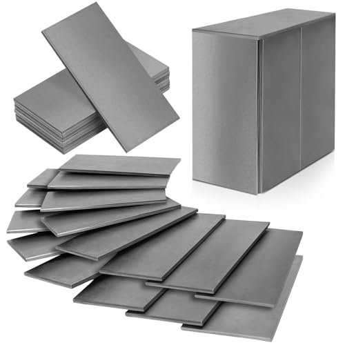
Coopay 12-Pack Welding Practice Kit with Steel Plates

- ✓ Durable mild steel
- ✓ Easy to weld and cut
- ✓ Good for multiple welding methods
- ✕ Limited size options
- ✕ Not suitable for large projects
| Material | 11 gauge mild steel (0.12″ / 0.3cm thick) |
| Size | Approximately 2″ x 4″ (5cm x 10cm) |
| Number of Coupons | 12 pieces |
| Welding Compatibility | Suitable for MIG, TIG, and manual Arc welding |
| Application | Training, practice welding, DIY repairs in construction, automotive, and household appliances |
| Edge Quality | Smooth and flat edges with good edge quality compared to stamped and cut steel |
Opening the box of the Coopay 12-Pack Welding Practice Kit, I immediately noticed how compact and well-organized the set is. The 12 steel coupons are neatly stacked, each about 2” x 4”, with a sturdy yet lightweight feel.
The smooth edges of the mild steel plates catch your eye—they seem ready for welding right out of the package.
Handling the coupons, I appreciated their thickness—11 gauge steel—that offers a solid feel without being cumbersome. The size is perfect for quick practice sessions, fitting comfortably in your hand or workspace.
The steel’s surface is smooth, making it easy to weld and ensuring clean, flat seams. It’s clear that this kit is designed for both beginners and those wanting to refine their skills.
Welding on these coupons was surprisingly straightforward. The mild steel performed well across MIG, TIG, and manual arc welding, with minimal warping or cracking.
I even tried repairing small household items, and the welds held strong. The smooth edges meant I didn’t need much finishing work—saving time and effort.
What I liked most is how versatile the kit is. Whether you’re practicing your bead or tackling more complex projects, these coupons give you a reliable platform.
Plus, the durability of the steel means you can reuse or re-weld on the same pieces without much fuss. Overall, a solid choice for honing your skills or trying out DIY repairs.
At $21.99, it’s an affordable way to get quality practice materials. If you’re serious about improving your welding or just getting started, this set offers good value and peace of mind.
Coopay 24-Pack Welding Practice Kit 11-Gauge Steel Coupons
- ✓ Good size and weight
- ✓ High-quality steel material
- ✓ Suitable for multiple welding types
- ✕ Limited number of coupons
- ✕ Not for advanced welding practice
| Material | 11-gauge mild steel (0.12″ / 0.3cm thick) |
| Dimensions | Approximately 2″ x 4″ (5cm x 10cm) |
| Number of Coupons | 24 pieces |
| Suitable For | MIG, TIG, and manual Arc welding practice |
| Application Fields | Construction, machinery manufacturing, automotive, household appliances |
| Welding Performance | Good weldability with minimal brittleness and deformation |
Ever struggled to find consistent practice materials that truly mimic real-world welding conditions? I grabbed the Coopay 24-Pack Welding Practice Kit, and right away, I appreciated how sturdy and well-made these coupons felt in my hand.
The 11-gauge steel is thick enough to give a realistic welding experience without being cumbersome to handle.
Each coupon measures about 2” x 4”, which is a perfect size for honing your skills without feeling overwhelmed. The smooth edges and flat surfaces make it easy to focus on your welds rather than fighting uneven or rough material.
I found it especially helpful for practicing MIG and TIG welds, as the steel holds heat well and shows weld quality clearly.
What really stood out is how versatile these coupons are. Whether you’re just starting out or looking to refine your technique, the variety of practice options suits both.
Plus, the fact that they’re suitable for repairing small home projects or practicing on complex mechanical parts makes them quite a value.
Using these, I noticed that the mild steel’s good weldability means fewer cracks or brittle spots, which often happen with cheaper materials. It’s a great way to build confidence before moving on to more challenging projects.
And the compact size makes storage and setup quick and easy, so you can fit practice into even tight schedules.
Overall, the kit offers a solid, realistic platform for anyone serious about improving their welds, whether in a hobby or professional setting. It’s a practical choice that bridges the gap between theory and real-world application, without breaking the bank.
What Are the Essential Aspects of Weld FEA?
The essential aspects of weld Finite Element Analysis (FEA) involve understanding the unique challenges presented by welded joints and ensuring accurate modeling and analysis.
- Material Properties: Accurately defining the material properties of both the base materials and the weld filler material is crucial, as welded joints can exhibit different mechanical behaviors than the base materials due to changes in microstructure. This includes understanding properties such as yield strength, ultimate tensile strength, and thermal expansion coefficients.
- Weld Geometry: The geometry of the weld, including its size, shape, and penetration depth, should be modeled accurately. This detail is vital because it significantly affects the stress distribution and load transfer within the joint, influencing the overall structural integrity.
- Boundary Conditions: Properly defining the boundary conditions and loading scenarios is essential for realistic FEA simulations. This includes specifying how the components are constrained and how loads are applied, which can significantly impact the results of the analysis.
- Thermal Effects: Considering the thermal effects of welding, such as residual stresses and distortions, is important. FEA should account for the heat input during welding, which can alter material properties and lead to thermal gradients that affect the performance of the weld.
- Meshing Techniques: Employing appropriate meshing techniques is vital for capturing the stress concentrations in welds. A finer mesh in the weld region may be necessary to accurately depict stress gradients, while a coarser mesh can be used in areas where stresses are more uniform.
- Validation and Verification: It is important to validate and verify the FEA results through experimental data or established benchmarks. This helps ensure that the analysis is accurate and reliable, providing confidence in the predictions made regarding the performance of the welded joints.
- Post-Processing Analysis: Effective post-processing of FEA results is necessary to interpret stresses, strains, and deformation patterns in the weld. This analysis helps identify potential failure modes and informs design improvements or modifications needed to enhance joint performance.
How Does Understanding Weld Types Enhance FEA Accuracy?
Understanding weld types is crucial for enhancing Finite Element Analysis (FEA) accuracy.
- Weld Geometry: The shape and size of the weld affect stress distribution and load transfer in the structure. Different geometries, such as fillet or butt welds, can lead to varying stress concentrations, which must be accurately modeled to ensure reliable FEA results.
- Material Properties: Each type of weld may have different material properties compared to the base metals. Understanding the mechanical characteristics, such as yield strength and ductility of the weld material, is vital for predicting failure modes and ensuring that the FEA reflects real-world behavior.
- Weld Quality and Defects: The presence of defects like cracks or porosity can significantly impact the integrity of the weld. Detailed knowledge of potential defects allows for a more precise simulation of the weld’s performance under load, enhancing the accuracy of the FEA results.
- Weld Stress Distribution: Different welding processes create varying residual stress profiles in the welded components. By understanding these profiles, engineers can better model the stress distribution within the FEA, leading to more accurate predictions of how the welded joint will perform in service.
- Thermal Effects: Welding introduces heat, which can alter the material properties and cause thermal expansion or contraction. Knowledge of how heat affects the surrounding material is essential to accurately simulate thermal stresses and distortions in FEA.
- Load Conditions: Different weld types may perform differently under various loading conditions such as tension, compression, or shear. Understanding how each weld type behaves under specific loads is critical for creating accurate FEA models that predict failure risks adequately.
Why is Accurate Geometry Representation Vital in Weld FEA?
The underlying mechanism involves the interaction between the weld material and the base materials, where discrepancies in geometry can lead to miscalculations of stress concentrations and failure points. For example, if a weld is modeled with an incorrect size or shape, the resulting FEA may underestimate or overestimate the strength and ductility of the joint, leading to potential structural failures. Additionally, accurate geometry helps in modeling thermal gradients during the welding process, which are crucial for understanding phase changes and microstructural evolution in the weld area. Therefore, precise representation is essential for achieving realistic simulation outcomes that reflect the actual behavior of welded structures under operational conditions.
What Strategies Can Improve Mesh Quality in Weld FEA?
Improving mesh quality in weld finite element analysis (FEA) involves several strategies that enhance accuracy and efficiency.
- Refining Mesh Density: Increasing the mesh density in areas of high stress concentration, such as weld joints, can significantly improve the accuracy of the FEA results. A finer mesh allows for better representation of the stress gradients around the weld area, leading to more reliable predictions of performance under load.
- Using Appropriate Element Types: Selecting the correct element types, such as 2D shell elements for thin-walled structures or 3D solid elements for thicker sections, is crucial for capturing the behavior of the weld. Each element type has its own advantages and is suited for specific geometries and loading conditions, which can enhance the overall fidelity of the analysis.
- Implementing Mesh Transitions: Gradually transitioning from finer mesh elements in critical areas to coarser elements in less critical regions helps balance computational efficiency with accuracy. This approach minimizes the total number of elements while maintaining sufficient detail where it matters most, thereby optimizing simulation time and resources.
- Utilizing Weld-Specific Element Formulations: Some FEA software provides specialized elements designed for modeling welds, which can capture the unique mechanical properties and behaviors of welded joints. These elements often account for the heat-affected zone and residual stresses, improving the simulation’s realism.
- Avoiding Distorted Elements: Ensuring that mesh elements are not overly distorted or skewed is vital for the accuracy of FEA results. Distorted elements can lead to convergence issues and inaccurate stress distributions, so it is important to check and refine the mesh to maintain a high-quality geometric representation.
- Defining Accurate Material Properties: Applying the correct material properties for both the base materials and the weld material is essential for realistic results. This includes accounting for variations in mechanical properties due to the welding process, such as changes in yield strength or ductility, which must be reflected in the mesh setup.
- Conducting Mesh Sensitivity Studies: Performing sensitivity studies helps identify the optimal mesh size and configuration by comparing results across different mesh densities. This practice ensures that the chosen mesh provides satisfactory results while avoiding unnecessary computational costs associated with overly fine meshes.
How Do Element Types and Sizes Affect FEA Results?
Mesh Size: A finer mesh can capture more complex stress distributions and geometric features, leading to more accurate results. However, a smaller mesh size results in increased computational time and resource requirements. Therefore, the challenge is to find an optimal balance between mesh size and computational efficiency.
Material Properties: In FEA, it is vital to accurately input material properties such as Young’s modulus, yield strength, and Poisson’s ratio, as these affect how elements react to loads. Inadequate representation of these properties can lead to significant deviations in predicted behavior and failure modes. Proper characterization of materials, especially for welds, is essential for realistic modeling.
Boundary Conditions: The application of boundary conditions must reflect the actual constraints and loading conditions the structure will experience in real life. Incorrectly applied boundary conditions can result in unrealistic deformations or stress concentrations, ultimately skewing the analysis results. Careful consideration of these conditions is crucial for accurate simulations.
Convergence Testing: Performing convergence tests involves refining the mesh until results stabilize, ensuring that they are independent of mesh size. This practice helps validate the adequacy of the chosen element type and mesh size in capturing the essential behavior of the structure. It is a critical step in ensuring that the FEA results are reliable and can be used for design decisions.
What Meshing Techniques Are Most Effective for Weld Analysis?
The most effective meshing techniques for weld analysis in finite element analysis (FEA) include:
- Refined Mesh at Weld Joints: Using a refined mesh around weld joints enhances the accuracy of stress concentration predictions. This technique involves creating smaller elements in regions where the weld is located, allowing for better representation of the complex stress fields that occur in these areas.
- Adaptive Meshing: Adaptive meshing techniques dynamically adjust the mesh density based on the analysis results. This approach allows for finer meshes to be created in high-stress regions while maintaining coarser meshes in areas of low stress, optimizing computational resources and improving solution accuracy.
- Multi-Scale Meshing: This technique integrates different mesh sizes to capture both global and local phenomena effectively. By using a coarser mesh for the bulk material and a finer mesh near the welds, it balances computational efficiency with the need for detailed analysis in critical areas.
- Mesh Sensitivity Analysis: Conducting a mesh sensitivity analysis ensures that the results are not significantly affected by the mesh size. By systematically refining the mesh and comparing results, engineers can determine the optimal mesh density that yields reliable results for weld analysis.
- Use of Weld-Specific Element Types: Utilizing elements specifically designed for welds can provide better fidelity in the simulation. These elements are tailored to account for the unique material properties and geometrical characteristics of welds, leading to more accurate predictions of performance under load.
How Can You Optimize Boundary Conditions in Weld FEA?
To optimize boundary conditions in weld Finite Element Analysis (FEA), consider the following best practices:
- Define Accurate Weld Geometry: Ensure that the weld geometry is modeled accurately in the FEA software to reflect the actual shape and size of the weld. This includes capturing any fillets, grooves, or other features that may influence the stress distribution during loading conditions.
- Apply Realistic Load and Boundary Conditions: Use loads and constraints that mimic the actual operating conditions of the welded structure. This involves considering factors such as thermal expansion, support locations, and any external forces that may affect the welded joint during service.
- Utilize Weld Material Properties: Assign appropriate material properties to the weld and base materials, including variations in strength, ductility, and thermal properties. Accurate material modeling is crucial, especially when assessing the heat-affected zone (HAZ) and the weld metal itself.
- Mesh Density Optimization: Use a finer mesh around the weld area to capture stress gradients accurately while balancing computational efficiency. A well-refined mesh can lead to more precise results, particularly in areas where high stress concentrations occur.
- Validate with Experimental Data: Whenever possible, compare FEA results with experimental data from physical tests of welded structures. This validation step can help identify discrepancies and refine the modeling approach to ensure reliability in the analysis.
What Common Mistakes Should Be Avoided When Defining Boundary Conditions?
When defining boundary conditions in weld Finite Element Analysis (FEA), certain common mistakes can lead to inaccurate results.
- Improperly defined constraints: Failing to accurately represent the physical constraints of the model can lead to unrealistic stress distributions. It is crucial to analyze how the actual welds are constrained in the physical world and replicate those conditions in the FEA model.
- Neglecting thermal effects: Ignoring the impact of heat generated during welding can significantly alter the material properties and stress states. Including thermal boundary conditions allows for a more accurate simulation of the weld process and its effects on the surrounding materials.
- Over-simplifying geometries: Reducing complex geometries to overly simplistic models can overlook critical stress concentrations. Ensure that the geometry used in the simulation reflects the actual components involved in the weld to avoid misrepresenting the mechanical behavior.
- Inadequate mesh refinement: Using a coarse mesh can lead to inaccurate results, especially around weld areas where gradients in stress and temperature are high. It’s important to refine the mesh in these regions to capture the necessary details of the weld joint behavior.
- Ignoring material properties: Not accounting for variations in material properties, such as yield strength and thermal expansion coefficients, can significantly impact simulation outcomes. Always ensure that the correct material properties are assigned based on the specific materials and conditions involved in the weld.
- Static loading assumptions: Assuming that loads are static when they may be dynamic can lead to incorrect predictions of performance. It is essential to consider the real loading conditions, including cyclic or impact loads, when setting boundary conditions in the analysis.
- Not validating results: Failing to compare simulation results with experimental data can prevent the identification of errors in the boundary conditions defined. Validation through testing or comparison with established benchmarks is necessary to ensure the reliability of the FEA results.
What Validation Techniques Are Effective for Ensuring Weld FEA Accuracy?
Effective validation techniques for ensuring weld FEA accuracy include:
- Experimental Validation: This involves comparing FEA results with physical test data from weld specimens. By conducting controlled experiments, such as tensile tests or fatigue tests, engineers can identify discrepancies and refine their FEA models to ensure they accurately represent real-world behavior.
- Benchmarking Against Established Models: Utilizing existing validated models as benchmarks helps to gauge the accuracy of new simulations. By comparing results from the new FEA with those from peer-reviewed or industry-standard models, engineers can assess the validity of their approach and make necessary adjustments to improve accuracy.
- Sensitivity Analysis: This technique examines how variations in input parameters affect the FEA results. By systematically changing parameters such as material properties, boundary conditions, and load applications, engineers can determine which elements have the most significant impact on the results, allowing for targeted improvements in model accuracy.
- Mesh Convergence Studies: Conducting mesh refinement studies ensures that the results are not overly dependent on the mesh size. By progressively refining the mesh and observing the changes in results, engineers can identify a mesh that provides stable results, thus confirming the reliability of the FEA outcomes.
- Nonlinear Analysis Techniques: Since welds often exhibit nonlinear behavior due to material properties and geometrical changes during loading, employing nonlinear analysis techniques is crucial. This approach can more accurately represent the actual performance of welded joints under various loading conditions, enhancing the fidelity of the FEA results.
- Peer Review and Collaboration: Engaging in peer reviews or collaborative studies with other engineers and researchers can provide fresh insights and identify potential flaws in the FEA approach. Sharing findings and methodologies fosters a culture of scrutiny that can enhance the overall credibility and accuracy of the simulation results.
How Can Experimental Data Be Used to Validate Weld FEA?
Experimental data plays a crucial role in validating finite element analysis (FEA) for welds by ensuring that the simulation results accurately reflect the real-world behavior of welded structures. The best practices for weld FEA regarding the use of experimental data include:
- Comparative Analysis: This involves comparing the FEA results with experimental outcomes to identify discrepancies. By conducting tests on welded samples and analyzing the stress distribution and deformation, engineers can assess the accuracy of their FEA models and make necessary adjustments.
- Calibration of Material Properties: Utilizing experimental data helps in calibrating the material properties used in FEA models. For instance, tensile tests on welded joints can provide precise yield and ultimate strength values, ensuring that the simulation accurately reflects the material behavior under load.
- Load and Boundary Condition Verification: Experimental data can be used to verify the loads and boundary conditions applied in the FEA model. By replicating the same conditions in physical tests, engineers can ensure that the assumptions made in the simulation are valid and that the model is representative of real-world scenarios.
- Failure Mode Analysis: Experimental testing allows for the exploration of various failure modes in welded joints, such as ductile or brittle failure. By documenting these modes and comparing them with FEA predictions, engineers can enhance the robustness of their models and refine their design processes.
- Sensitivity Studies: Experimental data can inform sensitivity studies, which examine how changes in weld parameters (e.g., heat input, filler material) affect the FEA results. This practice helps in understanding the influence of various factors on weld performance and optimizing the welding process accordingly.
Which Software Tools Provide the Best Results for Weld FEA?
Abaqus stands out for its ability to handle complex material behaviors, making it ideal for applications where the weld materials exhibit significant nonlinearity. It also provides extensive support for user-defined materials and allows for the analysis of large deformations and complex loading scenarios.
SolidWorks Simulation integrates seamlessly with the SolidWorks CAD environment, allowing users to easily create and modify weld designs while analyzing their mechanical performance. This integration reduces the learning curve and enhances productivity for engineers already using SolidWorks for design.
COMSOL Multiphysics excels in scenarios where multiple physical phenomena interact during the welding process, such as heat transfer and structural mechanics. This capability allows for a more comprehensive understanding of how different factors affect the weld quality and performance.
Altair HyperWorks is known for its ability to perform optimization alongside simulation, enabling engineers to refine their designs based on the FEA results. Its advanced meshing capabilities and solver options also enhance the accuracy of weld analysis, making it a reliable choice for industries focused on performance and efficiency.
What Features Should You Look for in Weld FEA Software?
When selecting weld FEA (Finite Element Analysis) software, several critical features should be considered to ensure effective analysis and simulation of welds.
- User-Friendly Interface: A clear and intuitive user interface allows for easier navigation and operation, which is crucial for both novice and experienced users. A well-designed interface helps reduce the learning curve and increases productivity by allowing users to focus on the analysis rather than struggling with software complexity.
- Robust Meshing Capabilities: Effective meshing is vital for accurate simulations, particularly in complex geometries associated with welded structures. The software should offer automatic meshing options and support for local refinement, enabling users to achieve a balance between computational efficiency and solution accuracy.
- Material Property Database: A comprehensive database of materials, including various metals and their welding characteristics, is essential for accurate simulation results. The software should allow users to define custom materials and their properties, including temperature-dependent behavior, to account for the effects of welding processes.
- Weld Modeling Features: The ability to accurately model different types of welds, such as fillet, groove, or spot welds, is crucial. The software should provide specific tools for defining weld geometry, heat input, and residual stresses, as these factors significantly influence the performance and integrity of welded joints.
- Thermal Analysis Capabilities: Since welding involves significant thermal effects, the software should include advanced thermal analysis features to simulate heat distribution and its impact on material properties. This capability helps predict issues like distortion, residual stresses, and phase changes resulting from welding.
- Nonlinear Analysis Support: Welded structures often experience nonlinear behavior due to material yield, geometry changes, and contact conditions. The software should support nonlinear analysis approaches to accurately capture these effects during the simulation of load conditions.
- Post-Processing Tools: Effective post-processing tools are necessary for interpreting and visualizing simulation results. The software should enable users to generate detailed reports, create graphs, and visualize stress distribution and deformation, facilitating comprehensive analysis and decision-making.
- Integration with CAD Software: Seamless integration with CAD (Computer-Aided Design) software streamlines the workflow from design to analysis. This feature allows users to import geometry directly, reducing the time spent on model preparation and minimizing errors during the transfer of designs.
- Technical Support and Community Resources: Access to reliable technical support and a robust community can be invaluable for users facing challenges or seeking to optimize their use of the software. Resources such as forums, tutorials, and documentation can enhance the user experience and provide guidance on best practices.